Technical Articles & Tools
1) LVD operating principle (schematic)
The shaped line beam enters the light valve; the LC under electrode control modulates/balances the field so multi-beam output meets the energy uniformity target (typically within 2%). This step is critical for exposure uniformity.
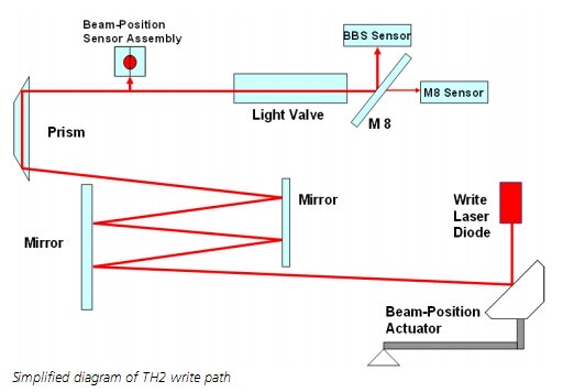
Schematic 1: optical path (schematic)
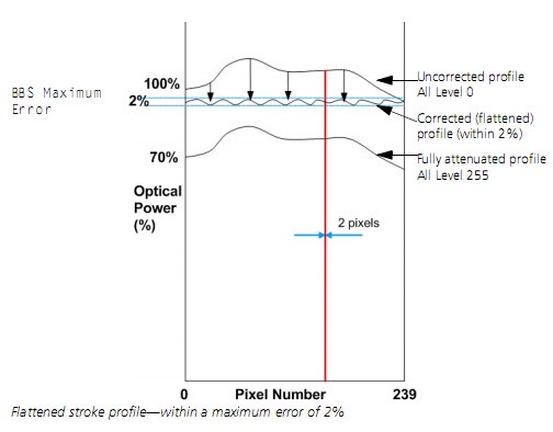
Schematic 2: light balance curve (schematic)
Schematic 3: electrodes/grid and modulation zone (schematic)
Note: When LVD electrode or LC layer state changes (oxidation, breakdown, contamination, aging), output energy uniformity often degrades, calibration becomes harder, or stable balance cannot be achieved.
2) Common failure causes
LVD damage usually comes from long-term use, and is accelerated in high temperature/humidity. Common causes include:
- Electrode oxidation: Long-term heat/moisture degrades conductive layer/electrode surface; contact and field distribution become abnormal.
- Breakdown: Local field concentration or defect leads to dielectric breakdown and irreversible damage.
- Burn/ablation: Hot spots or local energy concentration cause burn marks.
- Aging: LC or package material drift; modulation drops, balance range narrows or becomes unstable.
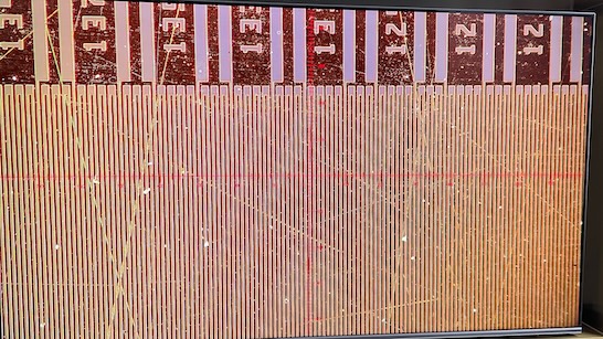
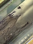
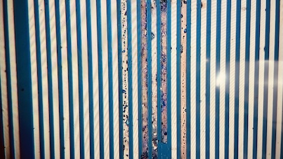
3) Failure examples (photos)
The four images below show typical LVD failure after long use: abnormal electrode areas, burn spots, contamination/corrosion, and local damage in the modulation zone.

Failure example 1
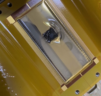
Failure example 2
Failure example 3
Failure example 4
4) Replacement notes (recommendations)
The LVD is a precision optical/electro-optical device. When replacing, follow these points to avoid secondary damage and "still unstable after replacement":
- Contamination control: Keep fingerprints, dust and oil out of the modulation zone; use clean tools and ESD precautions during handling and assembly.
- Moisture control: High humidity increases oxidation/corrosion risk; store dry and pack properly.
- Avoid extreme operation: Do not try excessive voltage/current/calibration before confirming status.
- Calibration: After LVD replacement, re-run energy balance calibration so the 224 beams meet the uniformity target.
Recommendation: If the environment is chronically hot and humid, also check dryer/cooling and sealing; otherwise a new LVD may age again quickly.